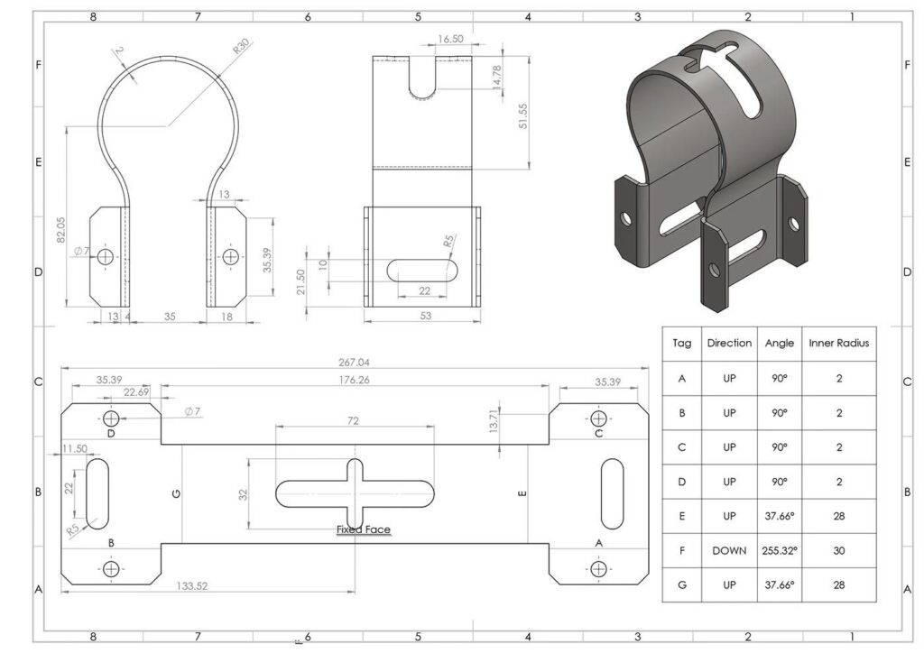
When working with sheet metal components in SOLIDWORKS, obtaining an accurate flat pattern is essential for successful manufacturing. One of the most important parameters affecting flat pattern calculations is the K-Factor.
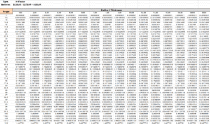
SOLIDWORKS provides different methods for calculating bend allowances, including the possibility of using custom Excel bend tables. By using a properly configured bend table, you can manage bending parameters and improve consistency across your sheet metal designs.
In this article, I’m sharing my Excel-based K-Factor bend table, developed for three commonly used structural steel grades:
-
- S235JR
-
- S275JR
-
- S355JR
The table covers sheet thicknesses from 1 mm to 20 mm and bending angles from 5° to 175°.
I’ll also explain what the K-Factor is, why it matters, and how to install and use the Excel file in SOLIDWORKS.
You can download the Excel file for free at the end of this article.
1. What Is the K-Factor in Sheet Metal Bending?
When a sheet metal component is bent, the material undergoes deformation.
The material on the outside of the bend is stretched, while the material on the inside is compressed.
Between these two regions, there is a theoretical layer called the neutral axis. Its length remains approximately unchanged during bending.
The K-Factor describes the position of this neutral axis relative to the total sheet thickness.
The formula is:
K-Factor = t / T
Where:
-
- K = K-Factor.
-
- t = Distance from the inside surface of the bend to the neutral axis.
-
- T = Total sheet thickness.
The K-Factor is dimensionless and typically has a value between 0 and 1.
It is an important parameter because it influences the bend allowance and, consequently, the developed flat pattern of a sheet metal component.
2. Why Is the K-Factor Important in SOLIDWORKS?
When designing sheet metal parts, the flat pattern must account for the material that stretches and compresses during bending.
If the K-Factor is incorrect, the calculated flat pattern may not match the dimensions required for manufacturing.
This can result in:
-
- Incorrect developed lengths.
-
- Dimensional inaccuracies after bending.
-
- Additional material waste.
-
- Problems during assembly.
-
- Increased manufacturing costs.
Using an appropriate K-Factor bend table helps make flat pattern calculations more consistent.
Instead of manually entering a single K-Factor for every component, SOLIDWORKS can use a bend table to determine the corresponding bending data according to the table structure.
3. Supported Materials: S235JR, S275JR and S355JR
This Excel bend table is intended for three commonly used European structural steel grades.
S235JR
S235JR is a general-purpose structural steel widely used in fabrication, mechanical structures and industrial applications.
S275JR
S275JR is a structural steel grade with higher minimum yield strength than S235JR. It is commonly used in structural and mechanical applications where additional strength is required.
S355JR
S355JR is a higher-strength structural steel used in applications requiring greater mechanical strength, including industrial equipment, machinery and structural components.
Why does the material grade matter?
Different steel grades can exhibit different springback characteristics during bending.
Springback is the partial recovery of the material after the bending force is removed.
The final bending result depends on several factors:
-
- Material grade and mechanical properties.
-
- Sheet thickness.
-
- Inside bend radius.
-
- Punch geometry.
-
- V-die opening.
-
- Bending method.
-
- Rolling direction.
-
- Material batch.
For this reason, selecting appropriate bending parameters for the material being processed is important.
Important: The K-Factor is not determined by the steel grade alone. Actual values should be established or validated for the specific material, tooling and bending conditions. The Excel table is intended as an engineering reference, not a universal manufacturing standard.
4. Excel K-Factor Bend Table – Specifications
I created this Excel file to provide a practical reference for sheet metal designers and manufacturing engineers working with S235JR, S275JR and S355JR.
The table covers a wide range of sheet thicknesses and bending angles.
| Parameter | Specification |
|---|---|
| Material grades | S235JR, S275JR, S355JR |
| Minimum thickness | 1 mm |
| Maximum thickness | 20 mm |
| Minimum bend angle | 5° |
| Maximum bend angle | 175° |
| File format | Excel |
| Application | SOLIDWORKS Sheet Metal |
The table is designed to help users manage K-Factor values for different sheet metal bending conditions.
It can also serve as a starting point for engineers who want to develop their own bending references based on their manufacturing processes.
5. How to Install the Excel Bend Table in SOLIDWORKS
After downloading the Excel file, you need to save it in an accessible directory and select it in the SOLIDWORKS Sheet Metal settings.
Follow these steps.
Step 1 – Download the Excel file
First, download the Excel K-Factor bend table using the download link provided in this article.
Save the file somewhere on your computer.
Step 2 – Copy the Excel file into your SOLIDWORKS directory
For easier file management, I recommend creating a dedicated folder for your sheet metal bend tables.
For example:
C:\SOLIDWORKS\Sheet Metal\Bend Tables\
Copy the downloaded Excel file into this folder.
You can also use an existing SOLIDWORKS bend table directory if you already have one.
Tip: Keep the original Excel file as a backup before making any modifications.
Step 3 – Open SOLIDWORKS
Start SOLIDWORKS and open your sheet metal part.
You can use an existing sheet metal component or create a new one using the Sheet Metal features.
Step 4 – Edit the Sheet-Metal feature
In the FeatureManager design tree:
-
- Locate the Sheet-Metal feature.
-
- Right-click on it.
-
- Select Edit Feature.
The Sheet Metal PropertyManager will open.
Step 5 – Select the Bend Table option
In the Sheet Metal PropertyManager, locate the Bend Allowance settings.
SOLIDWORKS provides different bend calculation methods.
Select Bend Table as the bend allowance calculation method.
Then browse for your downloaded Excel file.
Step 6 – Locate and select the Excel file
Navigate to the folder where you saved the Excel bend table.
For example:
C:\SOLIDWORKS\Sheet Metal\Bend Tables\
Select the Excel file and confirm your selection.
SOLIDWORKS will attempt to load the bend table.
If the file is correctly formatted and compatible with the selected table type and your SOLIDWORKS version, you can proceed with the sheet metal configuration.
Step 7 – Check your sheet metal parameters
Before confirming the settings, check the parameters of your sheet metal component.
Pay particular attention to:
-
- Sheet thickness.
-
- Inside bend radius.
-
- Material grade.
-
- Bend angle.
Make sure the thickness and bend angle are within the supported ranges of the Excel table.
For this table, the supported ranges are:
-
- Thickness: 1–20 mm.
-
- Bend angle: 5°–175°.
- Bend radius is equal to sheet thickness
Step 8 – Confirm and rebuild your model
After selecting the bend table:
-
- Confirm the Sheet-Metal feature.
-
- Rebuild the model using Ctrl + B or Ctrl + Q.
-
- Check the sheet metal geometry.
-
- Activate the Flat-Pattern feature.
-
- Review the resulting developed geometry.
SOLIDWORKS will use the bend table data according to its supported structure and configuration.
Step 9 – Check the flat pattern
Once the flat pattern has been generated, verify the developed dimensions.
For production applications, compare the calculated flat pattern with actual bending results.
If necessary, adjust the bending data based on measurements from real manufactured components.
Important: The Excel file must follow the specific SOLIDWORKS bend table format. A normal Excel spreadsheet containing K-Factor values is not automatically compatible with SOLIDWORKS. Make sure the file uses the appropriate structure, headers, worksheet organization and supported file extension.
6. How to Create Your Own K-Factor Bend Table
If you want to develop your own bend table, you can use Microsoft Excel to organize your bending data.
The general workflow is:
Step 1 – Define the materials
Identify the material grades you want to support, such as S235JR, S275JR and S355JR.
Step 2 – Define the thickness range
Create the required thickness values, starting from 1 mm and extending to 20 mm.
Step 3 – Define the bending angles
Create the angle range from 5° to 175°.
For example, you can use increments of 5°.
Step 4 – Enter the K-Factor values
Populate the table with values obtained from engineering calculations, material information or actual bending tests.
The values should reflect the relevant material and manufacturing conditions.
Step 5 – Validate the table
Compare the calculated flat patterns against real manufactured samples.
Adjust the data if the calculated developed lengths do not match the measured results.
Step 6 – Format the Excel file for SOLIDWORKS
Use a compatible SOLIDWORKS bend table structure.
Check the required worksheet layout and headers for your SOLIDWORKS version and bend table type.
7. Download the Free Excel K-Factor Bend Table
To help other mechanical designers, sheet metal engineers and SOLIDWORKS users, I’m sharing my Excel K-Factor bend table.
The file is intended for:
-
- S235JR structural steel.
-
- S275JR structural steel.
-
- S355JR structural steel.
-
- Sheet thicknesses from 1 mm to 20 mm.
-
- Bending angles from 5° to 175°.
- Bending radius = Sheet thickness
You can download the Excel file below:
8. Final Thoughts
Creating and managing a custom K-Factor bend table is a useful way to improve consistency in SOLIDWORKS sheet metal design.
When working with different steel grades and sheet thicknesses, having an organized bending reference can make the design process easier and help reduce flat pattern errors.
I hope this Excel tool will be useful to other SOLIDWORKS users, mechanical designers and sheet metal manufacturing engineers.
If you have any questions, suggestions or improvements, feel free to leave a comment below.
Happy designing!