Here is a brief work on Analysing CPU cooling system controller and deformation of the heat sink as a project for our lesson called Dynamics of Micromechanical Systems.

Dynamics of micro mechanical systems
February 2020
CPU cooling system
Why Cooling?
As a general rule, everything that consumes electricity heats up, this is called the Joule effect. That’s the electric energy which changes into another, thermal energy or heat (which is measured in Joule J). A processor does not escape this rule – unfortunately, it generates heat.
Rather than heat, we use thermal power to measure this phenomenon, which is the quantity of heat released during one second (in Joule, by second J/s or Watt W). Thermal power is a significant parameter, which is the one that is conveyed along the path: processor – > cooling system – > ambient air. If a processor releases a thermal power P, the ambient air ultimately receives the same thermal power, P.
For a processor, thermal power depends on three parameters:
- The electric voltage provided to the CPU
- The frequency
- The load
The released thermal power is proportional to the frequency (if each CPU’s cycle needs a certain quantity of energy, the more there are cycles in one second, the more the power dissipated by Joule effect is significant), to the load and to the square of the voltage. If these parameters increase, thermal power increases. Here things are getting worse, because one always seeks to obtain more megahertz!
Furthermore, to stabilize the processor at a higher frequency, increasing the voltage is essential (to improve the ratio signal/noise, electric noise being a byproduct of heat), which causes the CPU to produce an even more significant amount of thermal power!
A CPU will work at a given frequency only if its temperature is lower than a certain value, and the higher its frequency is, the lower this value is. But going down very low is useless – the silicon of the processor becomes insulating (nevertheless, it’s a long way to get there). Thus, temperature a very sensitive factor, and for this reason CPU needs to cool.
We will start with the basic concepts such as conduction, convection and a little bit of radiation, just to say that it exists because it plays only a negligible role for what concerns us. Next, basic concepts about the fluid’s interaction with cooling system components will be addressed, including pressure drop, fans and pumps.
We will then see the application of these principles to systems used daily to cool processors, like heatsinks. The goal of these articles is to have the necessary basis to describe the principles of the most common cooling system.
THERMAL CONDUCTION
Preamble:
In all the following articles, we assume that physical phenomenon coming into play are stationary, if none of the parameters considered will vary with time and the system is at equilibrium. Of course, reality is not like that – the processor will generate more or less heat according to whether it is more or less loaded. But then why neglect time related variations?
Well first, because it greatly simplifies things and second, because it roughly does not change anything in the final analysis. It is just enough to be concerned with what occurs when the CPU is fully loaded, when it generates the most thermal power, because what is valid under these conditions will also be in others.
Heat is not treated alone without reason; in other words, it propagates from hot to cold parts and tries to restore the thermal equilibrium, so that the temperature is uniform everywhere. For all the materials (solid or fluid), this phenomenon results when the body is motionless, in what is called Fourier’s Law. In order to be able to establish the principal characteristics of conduction, we will consider the simplest form of Fourier’s Law, applied to a very simple geometrical form – a very simple plate, which is heated uniformly on one of its faces.
We thus take a plate of some material, of thickness L (in meters, m) and with both greater surfaces having the same area A (in meters squared, m²) but having different temperatures. Other surfaces are supposed to be assumed thermally insulated so that all the heat flow which enters one of the large faces, exits from the other. Once again reality is different, the side faces will be generally exposed to the ambient air which will absorb heat, but so little that we can, without problem, adopt this assumption without modifying the range of what follows.
Fourier’s Law

The simplified version of Fourier’s Law gives a relationship between the thermal power P (W) which crosses the plate, the temperature difference between the hot face Th and the cold face Tc (in Kelvin K or Celsius degree °C; it doesn’t matter, as we will consider temperature differences), the surface A (m²), and the thickness L (m).
This law postulates that the thermal power is proportional to the temperature difference Th – Tc, to the surface area A, and inversely proportional to the thickness L. The proportionality factor is called thermal conductivity k and is thus measured in W/(m K); it generally varies with temperature and location, but for what we are concerned, these variations are very weak and we will consider thermal conductivity as a constant.
The following table presents the values of thermal conductivity for the most used materials, at ambient temperature:
| Material | Thermal conductivity in W/(m K) |
| Pure Diamond | 2000 |
| Pure Silver | 427 |
| Pure Copper | 399 |
| Pure Aluminum | 236 |
| Brass | 111 |
| Pure Iron | 81 |
| Pure Tin | 64 |
| Lead | 35 |
| Bronze | 26 |
| Water | 0.6 |
| PVC | 0.15 |
| Air | .027 |
Contact Resistance
With these two contacting plates, the formula used previously supposes they are in perfect contact, which would be the case if the two surfaces which make the interface between the two plates were perfectly flat and smooth. Once again, reality is cruel but here we can’t neglect it! Surfaces in contact are not smooth nor flat, they always have a rough pattern.
The effect of roughness is very important; in general, the real surface contact area is never higher than 2% of the interface surface area – yes 2%!!! This leaves enough places for micro cavities filled with air, which has a very bad thermal conductivity (see the table of conductivities above). All this thickness (0.5 – 60 μm for flat surfaces) consisting of roughness and air gaps form a thin layer which will conduct heat less; this translates into contact resistance Rc, which will depend upon:
- the form and the distribution of roughness (ie surface finish)
- the thermal conductivity of the air -or of the material- which fills the gaps (higher is better)
- the hardness of materials and the contact pressure between the two plates (softer materials and higher pressure allow to “crush” more easily roughness and thus offer a greater real surface contact area)
- the apparent interface surface area (a larger interface offers less resistance)
The Model
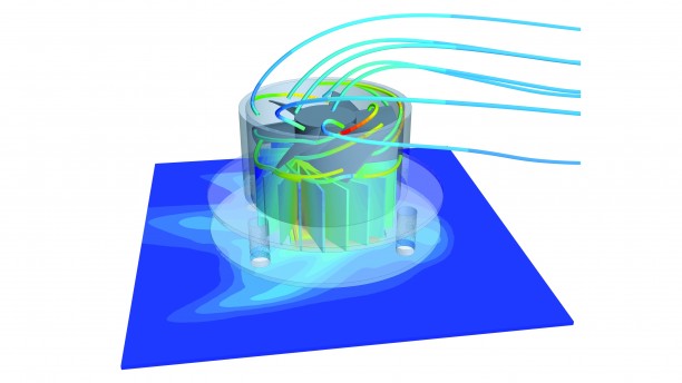
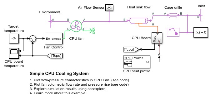
CPU Cooling System
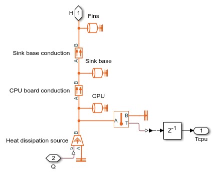
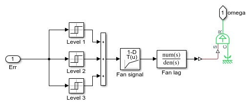
Here we simulated simple CPU cooling system using Matlab Simulink consists of a heat sink, a CPU fan, and fan controllers. The heat generated by the CPU is transferred to the heat sink by conduction and it is dissipated to the cooling air by forced convection mechanism. The heat sink is a parallel plate fin with rectangular fins between the plate fins. The CPU fan moves air across the heat sink by drawing air into the case grille from the outside and ejecting warm air from inside. The fan controller unit includes three control levels, representing a 3-speed switch, according to the CPU temperature. For lower CPU temperature, the fan speed is decreased and for higher temperature it is increased.
CPU Board Subsystem
Fan Control Subsystem
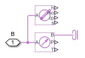
Air Flow Sensor Subsystem
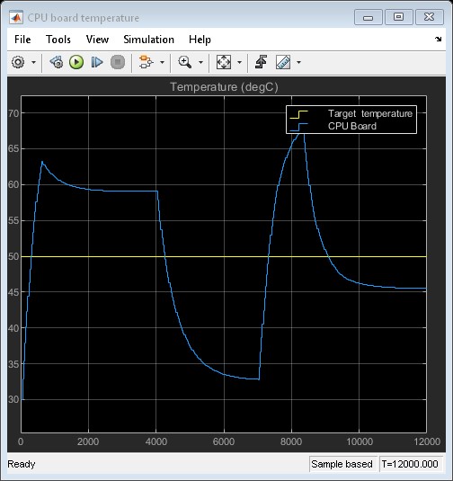
Simulation Results from Scopes
Simulation Results from Simscape Logging
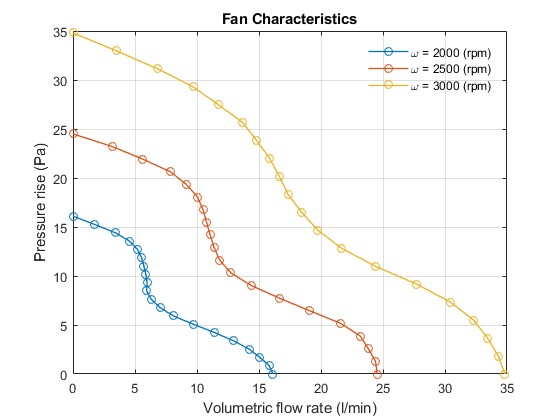
The plot below shows the volumetric flow rate – pressure rise characteristics of CPU fan.
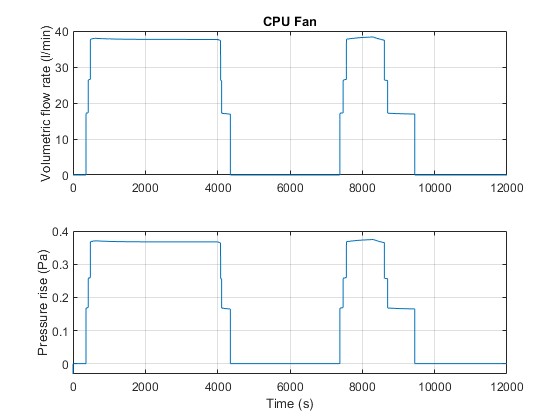
The plots below show the volumetric flow rate through and pressure rise across the CPU fan.
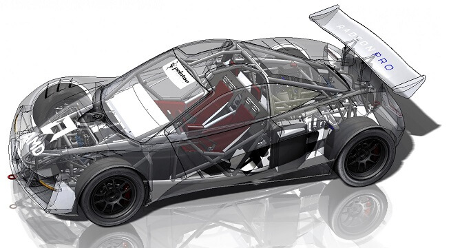
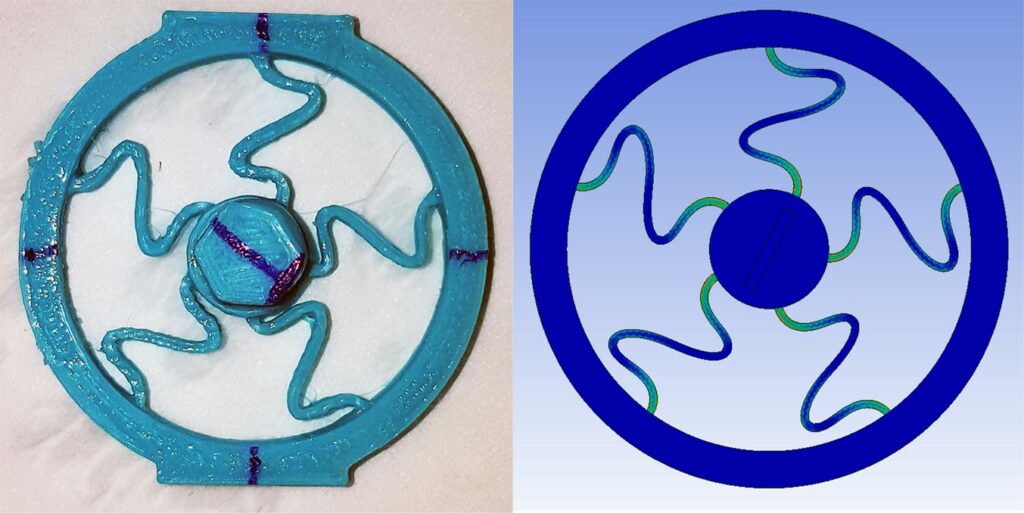
Heat sink Thermal stress analysis
Thermal-stress are stresses that are caused by increasing the temperature in a part. When temperature increase, the volume of part also increases which contradicts with fixed joints and surfaces. This may cause some fatigue failure or internal micro crack generation.
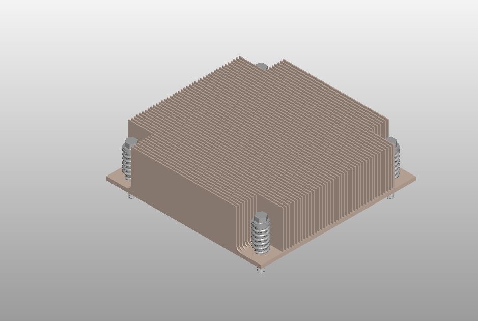
The Model
We used SolidWorks™ to model the CPU sink very close to the real part.
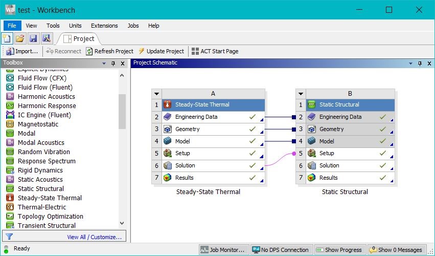
However, because Ansys academic is a limited software package we could not perform thermal stress analysis. The limit nodes number is 30,000 which is not enough for this model. So we simplified the model to be able to study it.
To perform Thermal-stress analysis, we used Ansys workbench. First we did a steady state
thermal analysis then we transferred the results to static structural component.
Results:
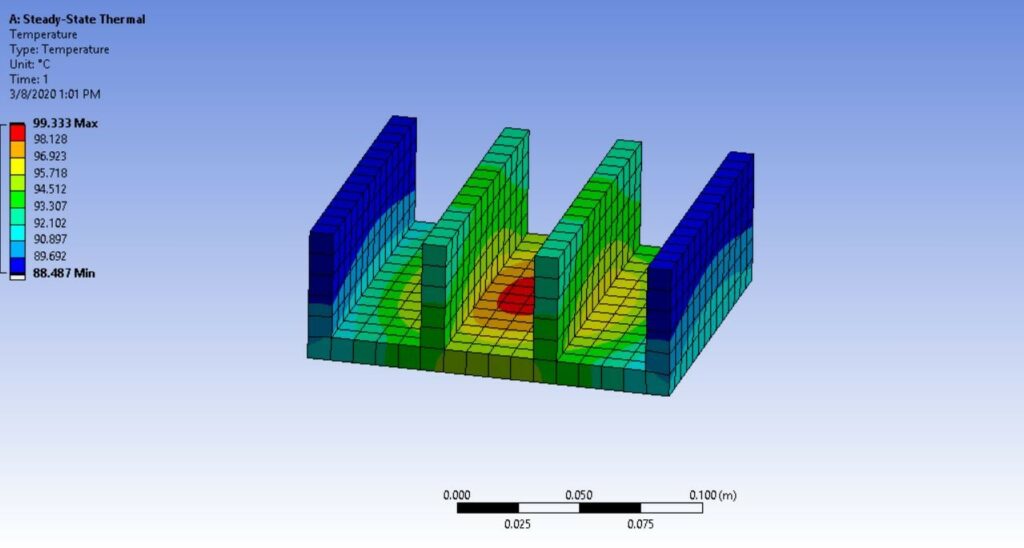
We consider the heat flow from a CPU at average load is 25 w.
First we assumed there is no Fan on the CPU sink so that the convection rate between air and fins is very low (10 W/m2). We also assumed that air temperature inside a computer case is 30c°. because of different heating elements it is usually more than room temperature.
This is the results without Fan.
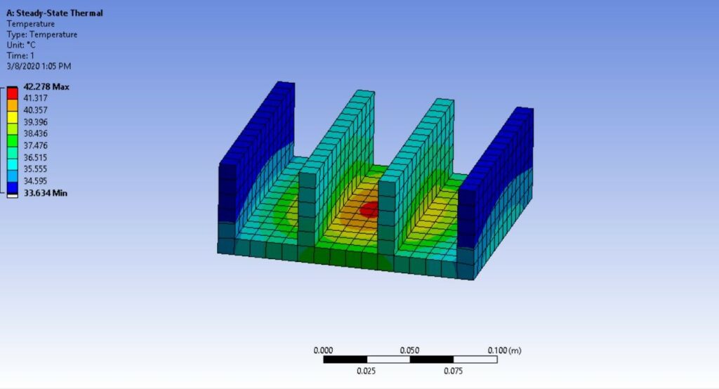
After adding a fan to system, the convection rate between air and fins will increase to 100 W/m2. This will result a very high cooling rate temperature will drop as seen in figure below.
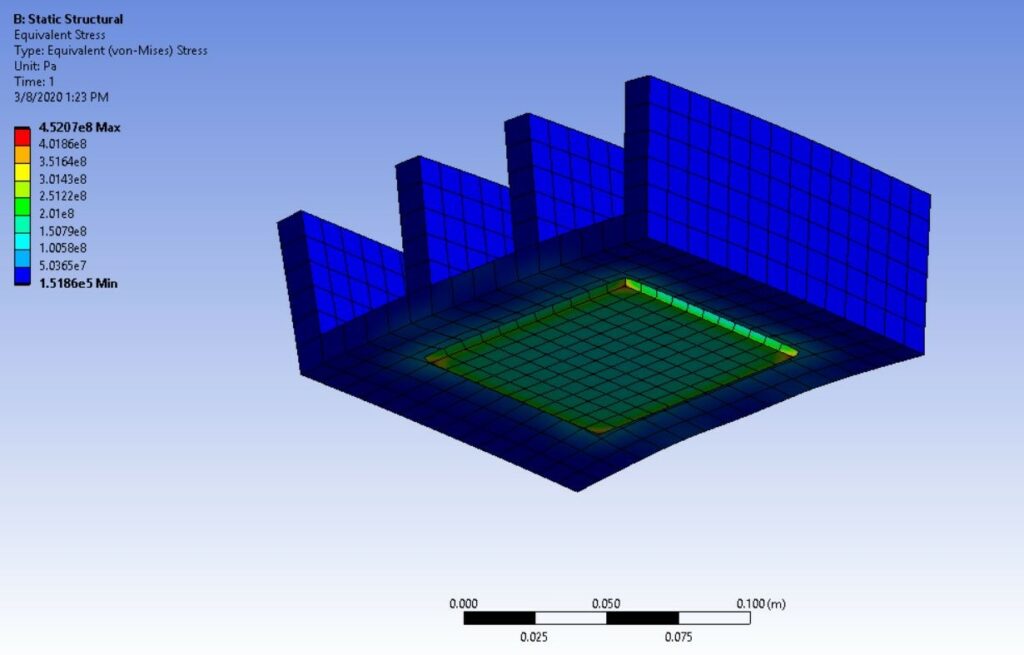
Finally, we transfer temperature results from steady state thermal analysis to static structural cell o study stresses. In the figure below We assume the coupling of heatsink and CPU unit is the only fixed support for heat sin. As you can see there is excessive stress which will cause coupling adhesive to fail.
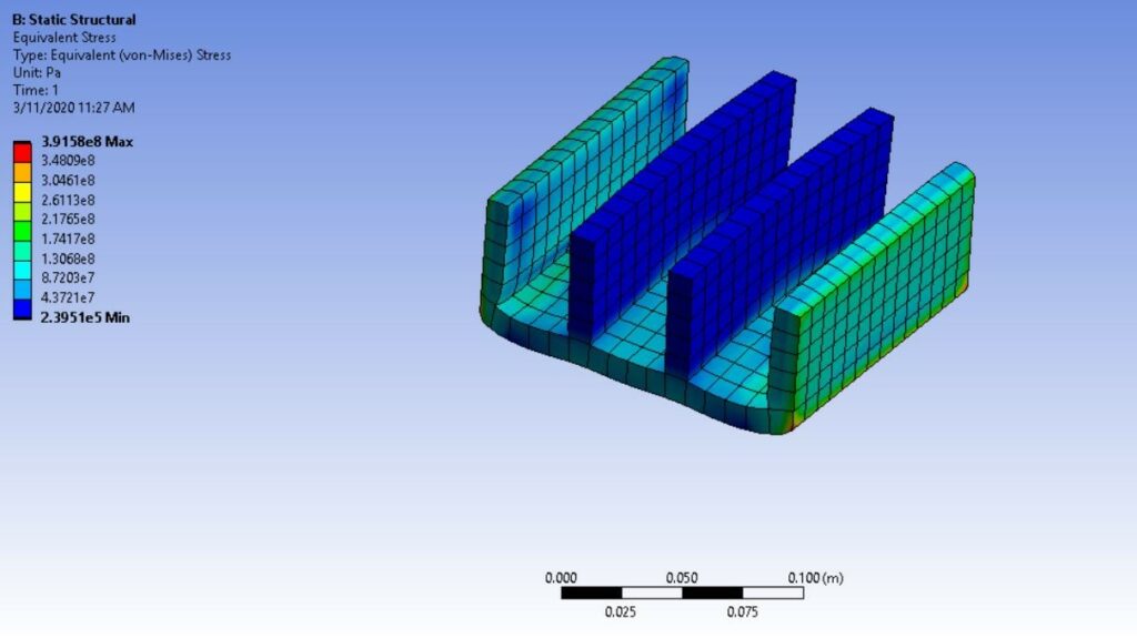
We added 2 more fixed supports to side surfaces to see the results and we see that maximum stress is lower in this case.
References:
International Journal of Mechanical Engineering and Technology (IJMET)
Volume 8, Issue 9, September 2017.
I find this tutorial very helpful for modeling the CPU fan and simulation of the flow.